Arduino 简明教程
Arduino - Reading Analog Voltage
此示例将向你展示如何在模拟引脚 0 上读取模拟输入。输入从 analogRead() 转换为电压,并打印到 Arduino 软件 (IDE) 的串行监视器。
This example will show you how to read an analog input on analog pin 0. The input is converted from analogRead() into voltage, and printed out to the serial monitor of the Arduino Software (IDE).
Components Required
您将需要以下组件:
You will need the following components −
-
1 × Breadboard
-
1 × Arduino Uno R3
-
1 × 5K variable resistor (potentiometer)
-
2 × Jumper
Procedure
按照电路图并将组件连接到面包板上,如下图所示。
Follow the circuit diagram and hook up the components on the breadboard as shown in the image given below.

Potentiometer
电位器(或电位计)是一种简单的机电传感器。它将输入操作者的旋转或线性运动转换为电阻变化。此变化(或可以)用于控制从立体声系统的音量到大型集装箱船的方向的任何事物。
A potentiometer (or pot) is a simple electro-mechanical transducer. It converts rotary or linear motion from the input operator into a change of resistance. This change is (or can be) used to control anything from the volume of a hi-fi system to the direction of a huge container ship.
我们所知的电位计最初被称为变阻器(基本上是一个可变绕线电阻器)。现有的各种电位计现在非常令人惊讶,对于初学者(特别是)来说,弄清楚哪种类型适合给定的任务可能非常困难。一些不同的电位计类型,所有这些类型都可以用于相同的任务,这使得这项工作更加困难。
The pot as we know it was originally known as a rheostat (essentially a variable wirewound resistor). The variety of available pots is now quite astonishing, and it can be very difficult for the beginner (in particular) to work out which type is suitable for a given task. A few different pot types, which can all be used for the same task makes the job harder.
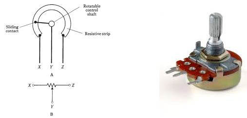
左侧图片显示了电位计的标准原理图符号。右侧图片是电位器。
The image on the left shows the standard schematic symbol of a pot. The image on the right is the potentiometer.
Sketch
在计算机上打开 Arduino IDE 软件。使用 Arduino 语言进行编码将控制您的电路。单击“新建”以新建一个草图文件。
Open the Arduino IDE software on your computer. Coding in the Arduino language will control your circuit. Open a new sketch File by clicking New.

Arduino Code
/*
   ReadAnalogVoltage
   Reads an analog input on pin 0, converts it to voltage,
   and prints the result to the serial monitor.
   Graphical representation is available using serial plotter (Tools > Serial Plotter menu)
   Attach the center pin of a potentiometer to pin A0, and the outside pins to +5V and ground.
*/

// the setup routine runs once when you press reset:

void setup() {
   // initialize serial communication at 9600 bits per second:
   Serial.begin(9600);
}

// the loop routine runs over and over again forever:

void loop() {
   // read the input on analog pin 0:
   int sensorValue = analogRead(A0);
   // Convert the analog reading (which goes from 0 - 1023) to a voltage (0 - 5V):
   float voltage = sensorValue * (5.0 / 1023.0);
   // print out the value you read:
   Serial.println(voltage);
}
Code to Note
在下面给出的程序或草图中,在设置函数中你首先做的事情是开始串行通信,在你的主板和你的计算机之间,传输速率为 9600 位/秒,行如下所示 −
In the program or sketch given below, the first thing that you do in the setup function is begin serial communications, at 9600 bits per second, between your board and your computer with the line −
Serial.begin(9600);在代码的主循环中,你需要建立一个变量来存储来自电位器的电阻值(介于 0 到 1023 之间,非常适合 int 数据类型)−
In the main loop of your code, you need to establish a variable to store the resistance value (which will be between 0 and 1023, perfect for an int datatype) coming from your potentiometer −
int sensorValue = analogRead(A0);要将值从 0-1023 更改为与电压相对应的范围,引脚正在读取,你需要创建另一个变量,一个 float,并进行一些计算。要在 0.0 和 5.0 之间缩放数字,将 5.0 除以 1023.0,然后将其乘以 sensorValue −
To change the values from 0-1023 to a range that corresponds to the voltage, the pin is reading, you need to create another variable, a float, and do a little calculation. To scale the numbers between 0.0 and 5.0, divide 5.0 by 1023.0 and multiply that by sensorValue −
float voltage= sensorValue * (5.0 / 1023.0);最后,你需要将此信息打印到你的串行窗口。你可以在代码的最后一行使用 Serial.println() 命令执行此操作 −
Finally, you need to print this information to your serial window. You can do this with the command Serial.println() in your last line of code −
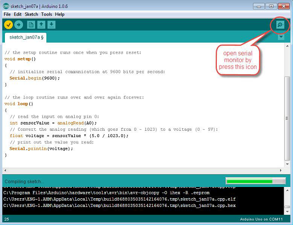
Serial.println(voltage)现在,通过单击顶部绿色栏右侧的图标或按 Ctrl+Shift+M,在 Arduino IDE 中打开串行监视器。
Now, open Serial Monitor in the Arduino IDE by clicking the icon on the right side of the top green bar or pressing Ctrl+Shift+M.