Digital-electronics 简明教程
Binary to Gray Code Converter
二进制到格雷码转换器是一种可以将二进制码转换为其等效格雷码的代码转换器类型。
A binary-to-gray code converter is a type of code converter that can translate a binary code into its equivalent gray code.
二进制到格雷码转换器接受二进制数作为输入,并生成相应的格雷码作为输出。
The binary-to-gray code converter accepts a binary number as input and produces a corresponding gray code as output.
以下是解释 4 位二进制到格雷码转换器操作的真值表。
Here is the truth table explaining the operation of a 4-bit binary-to-gray code converter.
Binary Code |
Gray Code |
B3 |
B2 |
B1 |
B0 |
G3 |
G2 |
G1 |
G0 |
0 |
0 |
0 |
0 |
0 |
0 |
0 |
0 |
0 |
0 |
0 |
1 |
0 |
0 |
0 |
1 |
0 |
0 |
1 |
0 |
0 |
0 |
1 |
1 |
0 |
0 |
1 |
1 |
0 |
0 |
1 |
0 |
0 |
1 |
0 |
0 |
0 |
1 |
1 |
0 |
0 |
1 |
0 |
1 |
0 |
1 |
1 |
1 |
0 |
1 |
1 |
0 |
0 |
1 |
0 |
1 |
0 |
1 |
1 |
1 |
0 |
1 |
0 |
0 |
1 |
0 |
0 |
0 |
1 |
1 |
0 |
0 |
1 |
0 |
0 |
1 |
1 |
1 |
0 |
1 |
1 |
0 |
1 |
0 |
1 |
1 |
1 |
1 |
1 |
0 |
1 |
1 |
1 |
1 |
1 |
0 |
1 |
1 |
0 |
0 |
1 |
0 |
1 |
0 |
1 |
1 |
0 |
1 |
1 |
0 |
1 |
1 |
1 |
1 |
1 |
0 |
1 |
0 |
0 |
1 |
1 |
1 |
1 |
1 |
1 |
0 |
0 |
0 |
让我们导出格雷码输出位的布尔表达式。为此,我们将使用 K 映射技术简化真值表。
Let us derive the Boolean expressions for the gray code output bits. For this, we will simplify the truth table using the K-map technique.
K-Map for Gray Code Bit G0
获得格雷码位 G0 的布尔表达式的 K 映射简化如下图所示。
The K-Map simplification to obtain the Boolean expression for the gray code bit G0 is shown in the following figure.
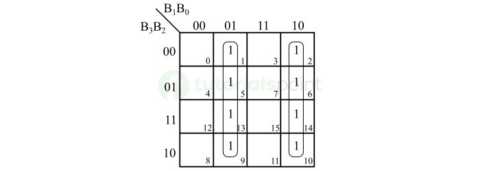
因此,格雷码位 G0 的布尔表达式为,
Hence, the Boolean expression for the gray code bit G0 is,
\mathrm{G_{0} \: = \: \overline{B_{1}} \: B_{0} \: + \ B_{1} \: \overline{B_{0}} \: = \: B_{0} \: \oplus \: B_{1}}
K-Map for Gray Code Bit G1
格雷码位 G1 的 K 映射简化如下 −
The K-Map simplification for the gray code bit G1 is shown below −
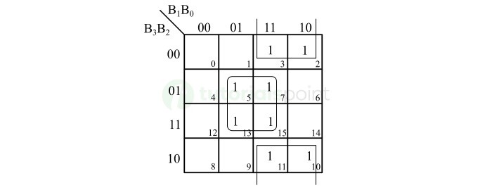
因此,格雷码位 G1 的布尔表达式为,
Thus, the Boolean expression for the gray code bit G1 is,
\mathrm{G_{1} \: = \: \overline{B_{2}} \: B_{1} \: + \ B_{2} \: \overline{B_{1}} \: = \: B_{1} \: \oplus \: B_{2}}
K-Map for Gray Code Bit G2
格雷码位 G2 的 K 映射简化如下图所示 −
The K-Map simplification for the gray code bit G2 is depicted in the following figure −
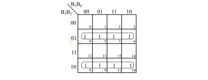
格雷码位 G2 的布尔表达式为,
The Boolean expression for the gray code bit G2 will be,
\mathrm{G_{2} \: = \: \overline{B_{3}} \: B_{2} \: + \ B_{3} \: \overline{B_{2}} \: = \: B_{2} \: \oplus \: B_{3}}
K-Map for Gray Code Bit G3
格雷码位 G3 的 K 映射简化如下图所示 −
The K-Map simplification for the gray code bit G3 is shown in the following figure −
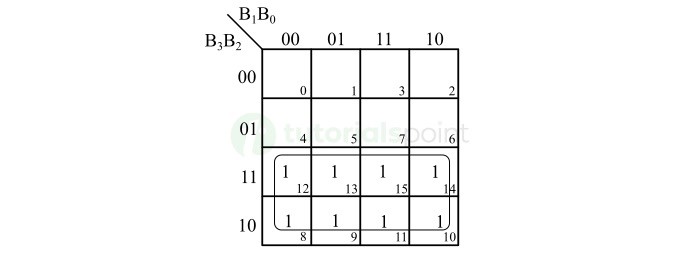
因此,格雷码位 G3 的布尔表达式为,
Hence, the Boolean expression for the gray code bit G3 is,
\mathrm{G_{3} \: = \: B_{3}}
现在,让我们利用这些布尔表达式来实现二进制到格雷码转换器的逻辑电路。
Let us now utilize these Boolean expressions to implement the logic circuit of the binary-to-gray code converter.
下图显示了 4 位二进制码到格雷码转换器的逻辑电路图 −
The following figure shows the logic circuit diagram of a 4-bit binary code to gray code converter −
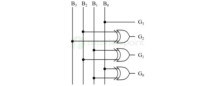
此电路可以将 4 位二进制数转换为等效的格雷码。
This circuit can convert a 4-bit binary number into an equivalent gray code.
我们可以遵循相同的程序来为任意数量的位设计二进制到格雷码转换器。
We can follow the same procedure to design a binary-to-gray code converter for any number of bits.