Digital-electronics 简明教程
Digital Electronics - Latches
锁存器是一个异步顺序电路,其输出会随施加输入的变化而立即变化。锁存器用于在数字系统中存储 1 位信息,因此它被认为是最基本的存储单元。
A latch is an asynchronous sequential circuit whose output changes immediately with the change in the applied input. A latch is used to store 1 bit information in a digital system, so it is considered as the most elementary memory element.
在本章中,我们将详细解释 latches in digital electronics 以及它们类型和应用。
In this chapter, we will explain in detail about latches in digital electronics along with their types and applications.
What is a Latch?
在数字电子学中, latch 是一个可以存储 1 位信息的异步顺序电路。它用作数字电路中的基本存储单元。
In digital electronics, a latch is an asynchronous sequential circuit that can store 1-bit information. It is used as the fundamental memory element in digital circuits.
锁存器可以有两种稳定状态,即 set 和 reset 。设定状态由逻辑 1 表示,复位状态由逻辑 0 表示。由于这两种稳定状态,锁存器也称为 bistable-multivibrator 。锁存器状态根据施加的输入进行切换。
A latch can have two stable states namely, set and reset. The set state is denoted by the logic 1 and the reset state is represented by the logic 0. Due to these two stable states, a latch is also known as a bistable-multivibrator. The state of a latch toggles according to the applied input.
关于锁存器要注意的最重要的事情是它们没有用于同步的时钟信号。这就是它们被称为异步顺序电路的原因。
The most important thing to be noted about latches is that they do not have a clock signal for synchronization. That is why they are called asynchronous sequential circuits.
逻辑门是锁存器的基本构建块。由于没有使用同步和时钟信号。因此,锁存器会立即根据输入信号的施加进行操作。
The logic gates are the fundamental building blocks of latches. Since there is no synchronization and clock signal used. Hence, the latches operate immediately on the application of input signals.
Characteristics of Latches
锁存器的一些关键特性如下所述 −
Some key characteristics of latches are explained below −
-
Latches can store 1-bit of digital information that can be represented using either logic 0 or logic 1. Thus, the latches are mainly used as memory elements in digital circuits.
-
Latches have a feedback mechanism that allows them to maintain their current state as it is until the next input is applied.
-
The operation of latches is completely controlled by applied inputs that means the output of the latches updates based on the change in the input signals.
Types of Latches
以下是数字电路和系统中使用的锁存器的主要类型 −
The following are the main types of latches that used in digital circuits and systems −
-
SR Latch
-
JK Latch
-
D Latch
-
T Latch
现在让我们详细讨论每种类型的锁存器。
Let us now discuss about each type of latch in detail.
SR Latch
SR 锁存器是一种具有两个输入线(指定为 S 和 R)的锁存器类型。其中,S 表示设定输入,R 表示复位输入。因此,它也被称为 Set-Reset Latch 。
The SR latch is a type of latch which has two input lines designated as S and R. Where, S represents the Set input and R represents the Reset input. Thus, it is also known as Set-Reset Latch.
SR 锁存器有两个稳定状态,即设定状态 (S) 和复位状态 ®。SR 锁存器的框图如图所示。
The SR latch has two stable states namely Set state (S) and Reset state ®. The block diagram of the SR latch is shown in the following figure.

就 SR 锁存器而言,S 输入将输出 Q 设定为 1,而 Q' 为 0。另一方面,R 输入将输出 Q 设定为 0,而 Q' 为 1。如果 S 和 R 输入同时为高,则称锁存器处于“禁止状态”。
In the case of SR latch, the S input sets the output Q to 1 and Q' to 0. On the other hand, the R input sets the output Q to 0 and Q' to 1. In case, when both S and R inputs are high, the latch is said to be in forbidden state.
SR 锁存器针对不同输入组合的完全操作由下述真值表描述−
The complete operation of the SR latch for different input combinations is described in the following truth table −
Inputs |
Outputs |
Comment |
S |
R |
Q |
Q' |
0 |
0 |
Q |
Q' |
No change |
0 |
1 |
0 |
1 |
Reset state |
1 |
0 |
1 |
0 |
Set state |
1 |
1 |
X |
X |
Forbidden state |
SR 锁存器可以通过以交叉耦合的方式连接两个 NOR 门来实现,如下述图表所示。
The SR latch can be implemented by connecting two NOR gates in a cross-coupled manner as shown in the following figure.

JK Latch
JK 锁存器是另一种类型的锁存器,它有两个输入,即 J 和 K。此处,输入 J 类似于 SR 锁存器中的 S 输入,输入 K 类似于 SR 锁存器中的 R 输入。
The JK latch is another type of latch which has two inputs namely, J and K. Here, the input J is similar to S input and the input K is similar to R input in an SR latch.
JK 锁存器的操作与 SR 锁存器类似,但它没有禁用状态。相反,当两个输入 J 和 K 均为 1 时,它具有一个切换状态,其中输出 Q 和 Q’会交换其状态。
The operation of the JK latch is similar to that of the SR latch but it does not have the forbidden state. Instead, it has a toggle state in which the outputs Q and Q' swap their states when both inputs J and K are 1.
因此,JK 锁存器主要设计用于克服 SR 锁存器中的禁用状态问题。
Therefor, the JK latch is mainly designed to overcome the problem of forbidden state in the SR latch.
JK 锁存器的框图如下述图表所示−
The block diagram of the JK latch is shown in the following figure −

下述真值表描述了 JK 锁存器针对不同输入组合的操作−
The truth table given below describes the operation of the JK latch for different input combinations −
Inputs |
Outputs |
Comment |
J |
K |
Q |
Q' |
0 |
0 |
Q |
Q' |
No change |
0 |
1 |
0 |
1 |
Reset state |
1 |
0 |
1 |
0 |
Set state |
1 |
1 |
Q' |
Q |
Toggle state |
从这个真值表,可以清楚地看出,通过实现切换状态来解决禁用状态问题。
From this truth table, it is clear that the problem of forbidden state is addressed by implementing the toggle state.
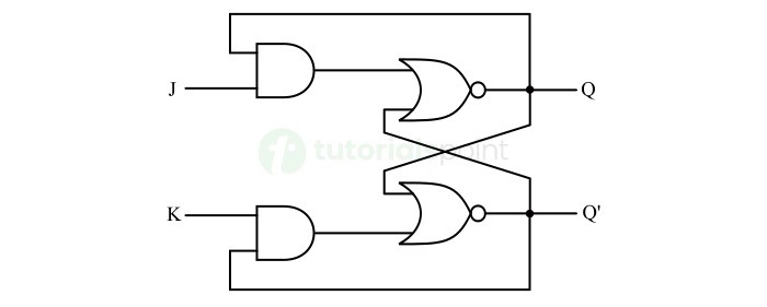
JK 锁存器的逻辑电路由两个 NOR 门和两个 AND 门的组合组成,如下述图表所示。
The logic circuit of the JK latch consists of a combination of two NOR gates and two AND gates as shown in the following figure.

D Latch
D 锁存器,也称为数据锁存器或透明锁存器,是一种双稳态多谐振荡器,它有两个输入信号,即 D(数据)输入和 E(使能)输入。
The D Latch, also known as Data latch or transparent latch, is a type of bistable multivibrator which has two input signals namely, D (Data) input and E (Enable) input.
只要 E 输入为高电平,那么 D 锁存器的输出 Q 与施加到 D 输入线路的输入相同。当 E 输入变为低电平时,D 锁存器的输出将保持不变,直至新输入施加到 D 输入。
The output Q of the D latch is same as the input applied at the D input line as long as the E input is high. When the E input goes low, the output of the D latch is held as it is until the new input is applied to the D input.
D 锁存器的框图如下述图表所示。
The block diagram of the D latch is shown in the following figure.

下述真值表解释了 D 锁存器的操作−
The truth table given below explains the operation of the D latch −
Inputs |
Outputs |
Comment |
D |
E |
Q |
Q' |
0 |
0 |
Q |
Q' |
No change |
0 |
1 |
0 |
1 |
Reset state |
1 |
0 |
Q |
Q' |
No change |
1 |
1 |
1 |
0 |
Set state |
D 锁存器的逻辑电路图描绘如下述图表所示−
The logic circuit diagram of the D latch is depicted in the following figure −

T Latch
T 锁存器是一种锁存器,当逻辑 1 施加到其输入线路时,它会切换其输出状态 (Q)。因此,它也被称为 toggle latch 。
T latch is a type of latch that toggles its output state (Q) when a logic 1 is applied to its input line. Hence, it is also known as toggle latch.
T 锁存器通过将 JK 锁存器的 J 和 K 输入连接在一起来实现,如下述框图所示。
The T latch is implemented by connecting the J and K inputs of the JK latch together as shown in the following block diagram.

描述 T 锁存器操作的真值表如下所示−
The truth table describing the operation of the T latch is shown below −
Input |
Present State |
Next State |
T |
Q |
Q' |
Q |
Q' |
0 |
0 |
1 |
0 |
1 |
0 |
1 |
0 |
1 |
0 |
1 |
0 |
1 |
1 |
0 |
1 |
1 |
0 |
0 |
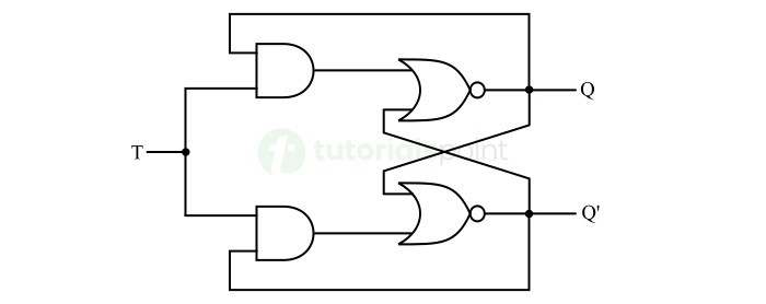
T 锁存器的逻辑电路图如下述图表所示−
The logic circuit diagram of the T latch is shown in the following figure −

Applications of Latches
锁存器在数字电子领域有若干应用。它们是最基本的存储组件,用于将一位信息存储在数字系统中。
The latches find several applications in the field of digital electronics. They are most elementary storage components used to store one bit of information in digital systems.
门控的一些常见应用如下:
Some of the common applications of latches are listed here −
-
Latches are used as 1-bit memory element in digital systems.
-
Latches are used to design digital registers which are employed for storage and manipulation of data in microprocessors and microcontrollers.
-
Latches are used to design flip-flops which are basically the synchronized latches.
-
Latches are also used in communication systems for temporary data storage or buffering purposes.
Conclusion
在本章中,我们解释了在数字系统中使用的不同类型门控,以及一些门控应用示例。
In this chapter, we explained different types of latches used in digital systems along with some examples of applications of latches.
总之,门控是一个由逻辑门构成的 1 位存储设备。它是一种异步顺序逻辑电路,没有同步时钟信号。
In conclusion, a latch is a 1-bit storage device made up of logic gates. It is a type of asynchronous sequential logic circuit which do not have a clocked signal for synchronization.
在数字系统中,门控用于执行一些关键功能,如临时数据存储、数据流控制等。
In digital systems, latches are used to serve some key functions like temporary data storage, data flow control, etc.