Digital-electronics 简明教程
Digital Electronics - Multiplexers
一种接受多个数据输入的数字逻辑电路,并且一次只能允许其中一个数据输入通过输出流动的电路称为 multiplexer or MUX 。本文旨在解释数字电子学中的多路复用器、其框图、功能和不同类型。因此,让我们从多路复用器的基本简介开始
A digital logic circuit that accepts several data inputs and allows only one of them at a time to flow through the output is called a multiplexer or MUX. This article is meant for explaining multiplexer in digital electronics, its block diagram, function, and different types. So, let us start with the basic introduction of multiplexer
What is a Multiplexer?
如前所述, multiplexer ,也称为 MUX ,是一个组合逻辑电路,旨在接受多个输入信号,并且只能通过输出线传输其中一个信号。简单来说,多路复用器是一种数字逻辑器件,它从 N 个(N = 2n)个输入数据源中选择一个并传输所选数据到单个输出线。
As already mentioned, a multiplexer, also referred to as MUX, is a combination logic circuit that is designed to accept multiple input signals and transfer only one of them through the output line. In simple words, a multiplexer is a digital logic device that selects one-out-of-N (N = 2n) input data sources and transmits the selected data to a single output line.
多路复用器也称为 data selector ,因为它从多个中选择一个。典型 2n:1 多路复用器的框图如图 1 所示。
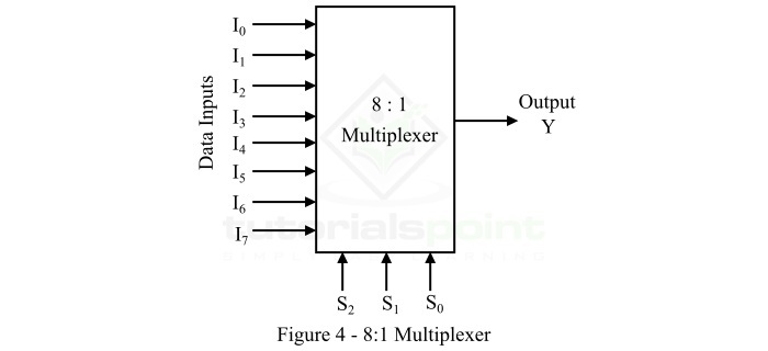
The multiplexer is also called data selector as it selects one from several. The block diagram of a typical 2n:1 multiplexer is shown in Figure 1.
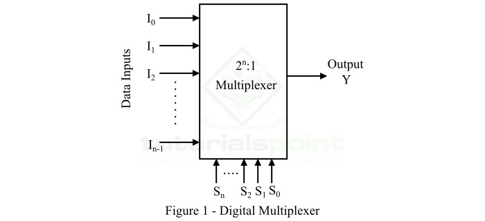
对于多路复用器,使用 SELECT lines 控制要通过输出线流动的所需数据输入的选择。在图 1 中的 MUX 框图中,I0、I1、… In-1,即 (2n) 是输入线, "n" 是选择线。这些选择线将确定要将哪个输入路由到输出。
In the case of multiplexer, the selection of desired data input to flow through the output line is controlled with the help of SELECT lines. In the block diagram of mux in Figure 1, I0, I1,… In-1, i.e., (2n) are the input lines, and "n" be the select lines. These select lines will determine which input is to be routed to the output.
因此,多路复用器作为一个多位置开关工作,其操作由数字信号控制。这些数字控制信号将施加到选择线上,以确定哪个数据输入将切换到输出线。
Hence, the multiplexer works as a multi-position switch whose operation is controlled by digital signals. These digital control signals are applied to the select lines to determine which data input will be switched to the output line.
Function of Multiplexer
多路复用器是一种数字逻辑器件,用于执行数据的 multiplexing 。其中,复用只是指数据的共享。从技术上讲,当从多个输入数据源中选择特定数据,并将所选数据传输到单个输出通道时,就称为 multiplexing 。
Multiplexer is a digital logic device which is used to perform multiplexing of data. Where, multiplexing simply means sharing of data. Technically, when a particular data is selected from multiple input data sources and transmitted the selected data to a single output channel, it is called multiplexing.
有多种复用类型,即 frequency multiplexing and time multiplexing 。
There are two types of multiplexing namely, frequency multiplexing and time multiplexing.
当多个设备连接到系统中的单个传输线时。在任何时间点,只有一个设备使用该线路传输数据,则这称为时分复用。另一方面,当多个设备共享一条公共线路以传输数据但频率不同时,称为频分复用。
When multiple devices are connected to a single transmission line in a system. At any point of time, only one device is using the line to transmit data, then this is called time multiplexing. On the other hand, when multiple devices share a common line to transmit data but at different frequencies, it is called frequency multiplexing.
Types of Multiplexers
根据输入数据线和选择线,多路复用器可以有多种类型。但在本文中,我们只讨论以下三种类型多路复用器−
Based on input data lines and select lines, the multiplexer can be of several types. But, in this article, we will discuss only the following three types of multiplexers −
-
2×1 Multiplexer
-
4×1 Multiplexer
让我们分别讨论这三种多路复用器。
Let us discuss each of these three multiplexers individually.
2×1 Multiplexer
2x1 多路复用器的框图如图 2 所示。2x1 多路复用器是基本的双输入多路复用器,它有两个数据输入线,分别指定为 I0 和 I1,一个用 S 表示的数据选择线,还有一条用 Y 表示的输出线。2x1 MUX 用于将两个 1 位数据源连接到一个公共地址。
The block diagram of a 2×1 multiplexer is shown in Figure 2. The 2×1 multiplexer is basic two input multiplexer which has two data input lines designated as I0 and I1, one data select line denoted by S and one output line denoted by Y. The 2×1 mux is used to connect two 1-bit data sources to a common designation.
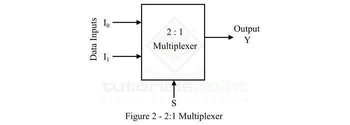
在 2x1 多路复用器中,施加到选择线 S 的数字信号的逻辑电平决定了哪个数据输入将通过输出线。2x1 多路复用器的操作可以从以下真值表中了解。
In the 2×1 multiplexer, the logic level of the digital signal applied to the select line S determines which data input will pass through the output line. The operation of the 2×1 multiplexer can be understood from the following truth table.
Select Line (S) |
Output (Y) |
0 |
I0 |
1 |
I1 |
4×1 Multiplexer
4×1 多路复用器有四个数据输入 I3、I2、I1 和 I0,两个选择线 s1 和 s0 和一个输出 Y。4×1 多路复用器的 block diagram 如下图所示。
4×1 Multiplexer has four data inputs I3, I2, I1 & I0, two selection lines s1 & s0 and one output Y. The block diagram of 4×1 Multiplexer is shown in the following figure.
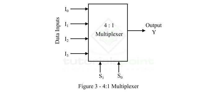
这 4 个输入之一将根据这两个选择线上存在的输入组合连接到输出。4×1 多路复用器的 Truth table 如下所示。
One of these 4 inputs will be connected to the output based on the combination of inputs present at these two selection lines. Truth table of 4×1 Multiplexer is shown below.
Selection Lines |
Output |
S1 |
S0 |
Y |
0 |
0 |
I0 |
0 |
1 |
I1 |
1 |
0 |
I2 |
1 |
1 |
从真值表中,我们可以直接编写输出 Boolean function ,Y 为
From Truth table, we can directly write the Boolean function for output, Y as
\mathrm{Y\:=\:{S_{1}}'{S_{0}}'I_{0}\:+\:{S_{1}}'S_{0}I_{1}\:+\:S_{1}{S_{0}}'I_{2}\:+\:S_{1}S_{0}I_{3}}
我们可以使用反相器、与门和或门实现此布尔函数。4×1 多路复用器的 circuit diagram 如下图所示。
We can implement this Boolean function using Inverters, AND gates & OR gate. The circuit diagram of 4×1 multiplexer is shown in the following figure.
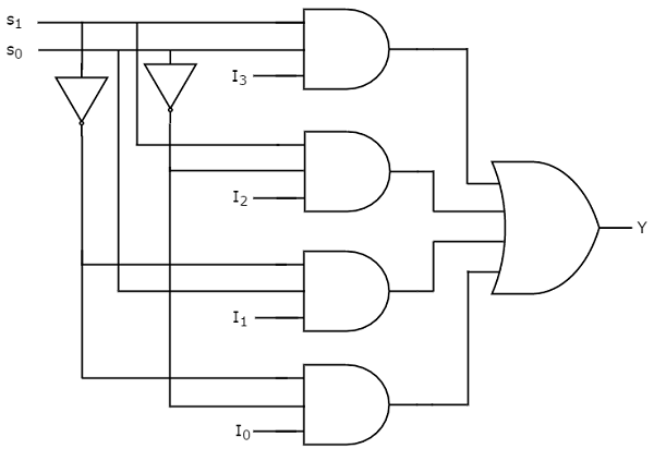
我们可以轻而易举地理解上述电路的运行。同样,您可以按照相同程序实现 8×1 多路复用器和 16×1 多路复用器。
We can easily understand the operation of the above circuit. Similarly, you can implement 8×1 Multiplexer and 16×1 multiplexer by following the same procedure.
Implementation of Higher-order Multiplexers
现在,让我们使用低级多路复用器来实现以下两个高级多路复用器。
Now, let us implement the following two higher-order Multiplexers using lower-order Multiplexers.
-
8×1 Multiplexer
-
16×1 Multiplexer
8×1 Multiplexer
在本节中,让我们使用 4×1 多路复用器和 2×1 多路复用器来实现 8×1 多路复用器。我们知道 4×1 多路复用器有 4 个数据输入、2 个选择线和一个输出。而 8×1 多路复用器有 8 个数据输入、3 个选择线和一个输出。
In this section, let us implement 8×1 Multiplexer using 4×1 Multiplexers and 2×1 Multiplexer. We know that 4×1 Multiplexer has 4 data inputs, 2 selection lines and one output. Whereas, 8×1 Multiplexer has 8 data inputs, 3 selection lines and one output.
因此,我们需要在第一级使用两个 4×1 Multiplexers 以获得 8 个数据输入。由于每个 4×1 多路复用器产生一个输出,因此我们需要在第二级中使用一个 2×1 Multiplexer ,将第一级的输出作为输入,并产生最终输出。
So, we require two 4×1 Multiplexers in first stage in order to get the 8 data inputs. Since, each 4×1 Multiplexer produces one output, we require a 2×1 Multiplexer in second stage by considering the outputs of first stage as inputs and to produce the final output.
设 8×1 多路复用器有八个数据输入 I7 到 I0、三个选择线 s2、s1 和 s0 以及一个输出 Y。8×1 多路复用器的 Truth table 如下所示。
Let the 8×1 Multiplexer has eight data inputs I7 to I0, three selection lines s2, s1 & s0 and one output Y. The Truth table of 8×1 Multiplexer is shown below.
Selection Inputs |
Output |
S2 |
S1 |
S0 |
Y |
0 |
0 |
0 |
I0 |
0 |
0 |
1 |
I1 |
0 |
1 |
0 |
I2 |
0 |
1 |
1 |
I3 |
1 |
0 |
0 |
I4 |
1 |
0 |
1 |
I5 |
1 |
1 |
0 |
I6 |
1 |
1 |
1 |
I7 |
我们可以通过考虑上方的真值表轻松地使用低阶多路复用器实现 8×1 多路复用器。8×1 多路复用器的 block diagram 如下图所示。
We can implement 8×1 Multiplexer using lower order Multiplexers easily by considering the above Truth table. The block diagram of 8×1 Multiplexer is shown in the following figure.
相同的 selection lines, s1 & s0 应用于两个 4×1 多路复用器。上层 4×1 多路复用器的数据输入是 I7 到 I4,下层 4×1 多路复用器的数据输入是 I3 到 I0。因此,每个 4×1 多路复用器都会根据选择线 s1 和 s0 的值产生一个输出。
The same selection lines, s1 & s0 are applied to both 4×1 Multiplexers. The data inputs of upper 4×1 Multiplexer are I7 to I4 and the data inputs of lower 4×1 Multiplexer are I3 to I0. Therefore, each 4×1 Multiplexer produces an output based on the values of selection lines, s1 & s0.
第一级 4×1 多路复用器的输出作为在第二级中出现的 2×1 多路复用器的输入。另一个 selection line, s2 应用于 2×1 多路复用器。
The outputs of first stage 4×1 Multiplexers are applied as inputs of 2×1 Multiplexer that is present in second stage. The other selection line, s2 is applied to 2×1 Multiplexer.
-
If s2 is zero, then the output of 2×1 Multiplexer will be one of the 4 inputs I3 to I0 based on the values of selection lines s1 & s0.
-
If s2 is one, then the output of 2×1 Multiplexer will be one of the 4 inputs I7 to I4 based on the values of selection lines s1 & s0.
因此,两个 4×1 多路复用器和一个 2×1 多路复用器的整体组合作为一个 8×1 多路复用器执行。
Therefore, the overall combination of two 4×1 Multiplexers and one 2×1 Multiplexer performs as one 8×1 Multiplexer.
16×1 Multiplexer
在本节中,让我们使用 8×1 多路复用器和 2×1 多路复用器来实现 16×1 多路复用器。我们知道 8×1 多路复用器有 8 个数据输入、3 个选择线和一个输出。而 16×1 多路复用器有 16 个数据输入、4 个选择线和一个输出。
In this section, let us implement 16×1 Multiplexer using 8×1 Multiplexers and 2×1 Multiplexer. We know that 8×1 Multiplexer has 8 data inputs, 3 selection lines and one output. Whereas, 16×1 Multiplexer has 16 data inputs, 4 selection lines and one output.
因此,我们需要在第一级中使用两个 8×1 Multiplexers 以获得 16 个数据输入。由于每个 8×1 多路复用器产生一个输出,因此我们需要在第二级中使用一个 2×1 多路复用器,将第一级的输出作为输入,并产生最终输出。
So, we require two 8×1 Multiplexers in first stage in order to get the 16 data inputs. Since, each 8×1 Multiplexer produces one output, we require a 2×1 Multiplexer in second stage by considering the outputs of first stage as inputs and to produce the final output.
设 16×1 多路复用器有十六个数据输入 I15 到 I0、四个选择线 s3 到 s0 和一个输出 Y。16×1 多路复用器的 Truth table 如下所示。
Let the 16×1 Multiplexer has sixteen data inputs I15 to I0, four selection lines s3 to s0 and one output Y. The Truth table of 16×1 Multiplexer is shown below.
Selection Inputs |
Output |
S3 |
S2 |
S1 |
S0 |
Y |
0 |
0 |
0 |
0 |
I0 |
0 |
0 |
0 |
1 |
I1 |
0 |
0 |
1 |
0 |
I2 |
0 |
0 |
1 |
1 |
I3 |
0 |
1 |
0 |
0 |
I4 |
0 |
1 |
0 |
1 |
I5 |
0 |
1 |
1 |
0 |
I6 |
0 |
1 |
1 |
1 |
I7 |
1 |
0 |
0 |
0 |
I8 |
1 |
0 |
0 |
1 |
I9 |
1 |
0 |
1 |
0 |
I10 |
1 |
0 |
1 |
1 |
I11 |
1 |
1 |
0 |
0 |
I12 |
1 |
1 |
0 |
1 |
I13 |
1 |
1 |
1 |
0 |
I14 |
1 |
1 |
1 |
1 |
我们可以通过考虑上述真值表,轻松地使用低阶多路复用器来实现 16×1 多路复用器。16×1 多路复用器的 block diagram 如下图所示。
We can implement 16×1 Multiplexer using lower order Multiplexers easily by considering the above Truth table. The block diagram of 16×1 Multiplexer is shown in the following figure.
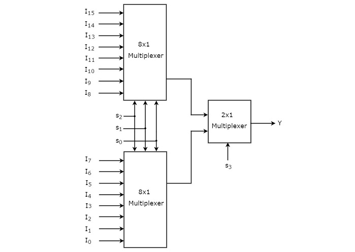
same selection lines, s2, s1 & s0 应用于这两个 8×1 多路复用器。上方的 8×1 多路复用器的数据输入为 I15 至 I8,而下方 8×1 多路复用器的数据输入为 I7 至 I0。因此,每个 8×1 多路复用器都会根据选择线路 s2、s1 和 s0 的值产生一个输出。
The same selection lines, s2, s1 & s0 are applied to both 8×1 Multiplexers. The data inputs of upper 8×1 Multiplexer are I15 to I8 and the data inputs of lower 8×1 Multiplexer are I7 to I0. Therefore, each 8×1 Multiplexer produces an output based on the values of selection lines, s2, s1 & s0.
第一级 8×1 多路复用器的输出用作第二级中 2×1 多路复用器的输入。另一个 selection line, s3 会应用于 2×1 多路复用器。
The outputs of first stage 8×1 Multiplexers are applied as inputs of 2×1 Multiplexer that is present in second stage. The other selection line, s3 is applied to 2×1 Multiplexer.
如果 s3 为零,那么 2×1 多路复用器的输出将是 8 个输入中的一个 Is7 至 I0,具体取决于选择线路 s2、s1 和 s0 的值。
If s3 is zero, then the output of 2×1 Multiplexer will be one of the 8 inputs Is7 to I0 based on the values of selection lines s2, s1 & s0.
如果 s3 为一,那么 2×1 多路复用器的输出将是 8 个输入中的一个 I15 至 I8,具体取决于选择线路 s2、s1 和 s0 的值。
If s3 is one, then the output of 2×1 Multiplexer will be one of the 8 inputs I15 to I8 based on the values of selection lines s2, s1 & s0.
因此,两个 8×1 多路复用器和一个 2×1 多路复用器的整体组合功能相当于一个 16×1 多路复用器。
Therefore, the overall combination of two 8×1 Multiplexers and one 2×1 Multiplexer performs as one 16×1 Multiplexer.
Applications of Multiplexers
在数字电子设备中,多路复用器在几乎所有类型的数字系统中都有许多应用。多路复用器的一些重要应用如下 −
In digital electronics, multiplexers have numerous applications in almost all types of digital systems. Some important applications of multiplexers are as follows −
-
Data routing and data selection
-
Parallel to series conversion
-
Logic function implementation
-
Generation of waveform, etc.